Editing Elements and Diagrams
Contents
- Editing Elements and Diagrams
- Editing Diagrams
- Editing Elements
- Formatting View Elements
- Change Font
- Change Line Color
- Change Fill Color
- Change Line Style
- Set Auto Resize
- Set Word Wrap
- Stereotype Display
- Show Visibility
- Show Namespace
- Show Property
- Show Type
- Show Multiplicity
- Show Operation Signature
- Suppress Attributes
- Suppress Operations
- Suppress Literals
- Aligning View Elements
- Layout Diagram
- Extending Elements
- Finding Model Elements
Editing Diagrams
Create Diagram
To create a Diagram:
- Select first an element where a new Diagram to be contained as a child in Explorer.
- Select Model | Add Diagram | <DiagramType> in Menu Bar or select Add Diagram | <DiagramType> in Context Menu.
Delete Diagram
To delete a Diagram:
- Select a Diagram to delete in Explorer.
- Press
Ctrl+Deleteor select Edit | Delete from Model in Menu Bar or Delete from Model in Context Menu.
Open Diagram
To open a diagram, double-click a diagram in Explorer.
Close Diagram
To close a diagram, click the close icon (x mark) of a diagram in Working Diagrams or press F4 or select View | Close Diagram in Menu Bar.
To close other diagram except a active diagram, press Ctrl+F4 or select View | Close Other Diagrams in Menu Bar.
To close all diagrams, press Shift+F4 or select View | Close All Diagrams in Menu Bar.
Change Active Diagram
To change active diagram, select a diagram in Working Diagram.
To activate the next diagram, press Ctrl+Shift+] or select View | Next Diagram.
To activate the previous diagram, press Ctrl+Shift+[ or select View | Previous Diagram.
Zoom In and Out
To zoom in the diagram, press Ctrl++ or select View | Zoom In in Menu Bar.
To zoom out the diagram, press Ctrl+- or select View | Zoom Out in Menu Bar.
To set zoom level to actual size, press Ctrl+0 or select View | Actual Size in Menu Bar.
You can check the current zoom level in StatusBar.
Editing Elements
Create Element
You have following options to create Model Elements and View Elements.
To create an Element from Toolbox:
- Select <ElementType> in Toolbox.
- Drag on the diagram as the size of element, or link two elements if the element is a kind of relationship.
Note
In most cases, creating an element from Toolbox means creating the both Model Element and View Element. For example, if you create a Class in a Diagram from Toolbox, a Class Model Element and a Class View Model which referencing the Model Element will be created. See Model vs. Diagram
If you have already Model Elements, you can create View Elements referencing the Model Element on a Diagram.
To create a View Model by Drag-and-Drop:
- Select a Model Element in Explorer.
- Drag the Model Element and drop on a Diagram.
To create a Model Element in Explorer:
- Select first an element where a new Model Element to be contained as a child in Explorer.
- Select Model | Add | <ElementType> in Menu Bar or select Add | <ElementType> in Context Menu.
Delete Elements
See also
- Model vs. Diagram
- Before deleting elements, you need to distinguish the difference of Model Element, View Element, and Diagram.
To delete View Elements in a Diagram.
- Select View Elements to be deleted in a Diagram.
- Press
Deleteor Select Edit | Delete in Menu Bar or Delete in Context Menu.
Note
Deleting View Elements do not delete Model Elements.
To delete Model Elements:
- Select Elements to be deleted in a Diagram or in Explorer.
- Press
Ctrl+Deleteor Select Edit | Delete from Model in Menu Bar or Delete from Model in Context Menu.
Note
Model Elements are always deleted with corresponding View Elements.
Select Elements
To select view elements in Diagram Editor:
You can select an Element in Diagram just by clicking on an Element. If you want to select additional elements while keeping current selections, click on element with pressing Shift.
When you drag an area, Elements overlaps the area will be selected. Pressing Shift also work with dragging.
If you want to select all elements in the Diagram, press Ctrl+A or select Edit | Select All in Menu Bar or Select All in Context Menu.
Note
Selecing an Element on a Diagram means selection of the both Model Element and View Element.
To select a model element in Explorer:
In Explorer, you can select a Model Element by clicking on an Element.
If you want to select an element in Explorer corresponding to the a selected element in Diagram, press Ctrl+E or select Edit | Select In Explorer in Menu Bar or Select In Explorer in Context Menu.
Copy and Paste
When copying or cutting elements for pasting, a clear distinction has to be made between model elements and view elements. If a model element is copied, it has to be pasted under a model element. In this case, all the sub-elements contained in the selected element are copied together. View elements can be copied within the same diagram or to different diagrams. Copied view elements can be pasted in diagrams only; they cannot be pasted to model elements. Copying and pasting may also be restricted depending on the view element types and diagram types.
To copy and paste view elements in Diagram Editor
- Select view elements in a diagram to copy. (You can select multiple elements. See Select Elements)
- Press
Ctrl+Cor select Edit | Copy in Menu Bar or Copy in Context Menu. (To cut view elements, pressCtrl+Xor select Edit | Cut in Menu Bar or Cut in Context Menu) - Open the diagram where the copied view elements to be pasted. (See open diagram??)
- Press
Ctrl+Vor select Edit | Paste in Menu Bar or Paste in Context Menu. The copied view elements will be pasted to the active diagram.
To copy and paste a model element in Explorer:
- Select a model element to copy in Explorer.
- Press
Ctrl+Cor select Edit | Copy in Menu Bar or Copy in Context Menu. (To cut view elements, pressCtrl+Xor select Edit | Cut in Menu Bar or Cut in Context Menu) - Select a model element where the copied element will be pasted in Explorer.
- Press
Ctrl+Vor select Edit | Paste in Menu Bar or Paste in Context Menu. The copied view elements will be pasted to the active diagram. The copied model element can be pasted in where an element is able to contain.
Note
Some elements are not allowed to copy, cut, and paste.
Undo and Redo
To undo an action, press Ctrl+Z or select Edit | Undo in Menu Bar.
To redo an undo-ed action, press Ctrl+Y or select Edit | Redo in Menu Bar.
Edit Properties
You can edit properties of model elements in Property Editor.
Documenting Elements
You can edit documentation of model elements in Documentation Editor.
Formatting View Elements
Change Font
To change font face, size, and color of view elements:
- Select view elements in diagram.
- Show FontDialog by pressing
Ctrl+Shift+For selecting Format | Font... in Menu Bar or Context Menu. - Select font face, size or color and press OK button.
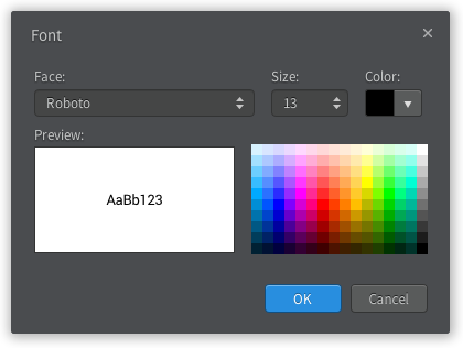
You can also use Style Editor to change Font face, size, and color.
Change Line Color
To change line color of view elements:
- Select view elements in diagram.
- Show ColorDialog for line color by pressing
Ctrl+Shift+Lor selecting Format | Line Color... in Menu Bar or Context Menu. - Select line color and press OK button.
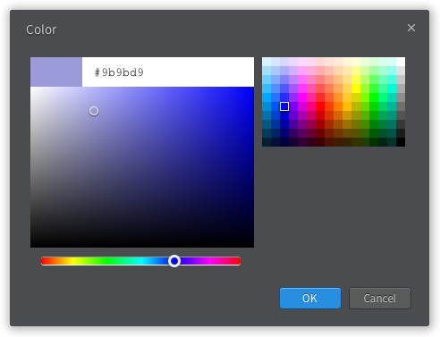
You can also use Style Editor to change line color.
Change Fill Color
To change fill color of view elements:
- Select view elements in diagram.
- Show ColorDialog for fill color by pressing
Ctrl+Shift+Ior selecting Format | Fill Color... in Menu Bar or Context Menu. - Select fill color and press OK button.
You can also use Style Editor to change fill color.
Change Line Style
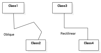
To change line style of view elements:
- Select view elements in diagram.
- Select one of line styles.
- Rectilinear - Press
Ctrl+Lor select Format | Line Style | Rectilinear in Menu Bar or Context Menu. - Oblique - Press
Ctrl+Bor select Format | Line Style | Oblique in Menu Bar or Context Menu.
- Rectilinear - Press
You can also use Style Editor to line style.
Set Auto Resize
To set view elements always resize automatically:
- Select view elements in diagram.
- Press
Ctrl+Shift+Ror check (or uncheck) Format | Auto Resize in Menu Bar or Context Menu.
You can also use Style Editor to line style.
Set Word Wrap
To allow text can be shown in multiple lines:
- Select view elements in diagram.
- Press
Ctrl+Shift+Wor check (or uncheck) Format | Word Wrap in Menu Bar or Context Menu.
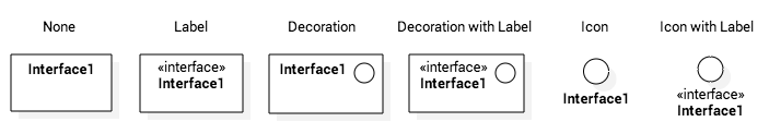
Stereotype Display
An element has six alternative representations based on the stereotype. To change stereotype display:
- Select view elements in diagram.
- Press
Ctrl+Shift+0~Ctrl+Shift+5or select Format | Stereotype Display | <StereotypeDisplayKind> in Menu Bar or Context Menu.
Supported stereotype display kinds are follow:
- None (
Ctrl+Shift+0) : Do not show stereotype. - Label (
Ctrl+Shift+1) : Show stereotype as a label. - Decoration (
Ctrl+Shift+2) : Show stereotype as a decorated icon on the top left. - Decoration with Label (
Ctrl+Shift+3) : Show stereotype as a label with a decorated icon. - Icon (
Ctrl+Shift+4) : Show element as a icon. - Icon with Label (
Ctrl+Shift+5) : Show element as a icon with label.
Show Visibility
To show (or hide) visibilities:
- Select view elements in diagram.
- Press
Ctrl+Shift+Vor check (or uncheck) Format | Show Visibility in Menu Bar or Context Menu.
Show Namespace
To show (or hide) namespace:
- Select view elements in diagram.
- Press
Ctrl+Shift+Nor check (or uncheck) Format | Show Namespace in Menu Bar or Context Menu.
Show Property
To show (or hide) properties:
- Select view elements in diagram.
- Press
Ctrl+Shift+Por check (or uncheck) Format | Show Property in Menu Bar or Context Menu.
Show Type
To show (or hide) types:
- Select view elements in diagram.
- Press
Ctrl+Shift+Yor check (or uncheck) Format | Show Type in Menu Bar or Context Menu.
Show Multiplicity
To show (or hide) multiplicities:
- Select view elements in diagram.
- Press
Ctrl+Shift+Mor check (or uncheck) Format | Show Multiplicity in Menu Bar or Context Menu.
Show Operation Signature
To show (or hide) operation signature:
- Select view elements in diagram.
- Press
Ctrl+Shift+Gor check (or uncheck) Format | Show Operation Signature in Menu Bar or Context Menu.
Suppress Attributes
To suppress attributes:
- Select view elements (e.g. Class) in diagram.
- Press
Ctrl+Shift+Aor check (or uncheck) Format | Suppress Attributes in Menu Bar or Context Menu.
Suppress Operations
To suppress operations:
- Select view elements (e.g. Class) in diagram.
- Press
Ctrl+Shift+Oor check (or uncheck) Format | Suppress Operations in Menu Bar or Context Menu.
Suppress Literals
To suppress literals:
- Select Enumeration view elements in diagram.
- Press
Ctrl+Shift+Tor check (or uncheck) Format | Suppress Literals in Menu Bar or Context Menu.
Aligning View Elements
To bring view elements on the front:
- Select view elements in diagram.
- Select Format | Alignment | Bring to Front in Menu Bar or Alignment | Bring to Front in Context Menu.
Or, to send view elements to the back:
- Select view elements in diagram.
- Select Format | Alignment | Send to Back in Menu Bar or Alignment | Send to Back in Context Menu.
And, you can align two or more view elements:
- Select view elements in diagram.
- Select Format | Alignment | <AlignmentKind> in Menu Bar or Alignment | <AlignmentKind> in Context Menu.
- Align Left : Align selected view elements to the left.
- Align Right : Align selected view elements to the right.
- Align Middle : Center selected view elements horizontally.
- Align Top : Align selected view elements to the top.
- Align Bottom : Align selected view elements to the bottom.
- Align Center : Center selected view elements vertically.
Layout Diagram
To layout diagram automatically:
- Open the diagram to be layout.
- Select Format | Layout | Auto in Menu Bar.
If you want to layout diagram in a particular direction:
- Open the diagram to be layout.
- Select Format | Layout | <Direction> in Menu Bar. Supported directions are Top to Bottom, Bottom to Top, Left to Right and Right to Left.
Extending Elements
Assign Stereotype
To assign defined stereotype to elements (e.g. defined in UML Standard Profile):
- Select model elements to assign stereotype.
- Click the magnifier icon on the right side of stereotype property in Property Editor.
- Select a stereotype in Element Picker Dialog.
To assign temporal stereotype to elements:
- Select model elements to assign stereotype.
- Enter stereotype name in stereotype property in Property Editor.
Add Constraints
To add a Constraint to an element:
- Select model elements to add a constraint.
- Select Model | Add | Constraint in Menu Bar or select Add | Constraint in Context Menu.
- Edit constraint in specification property in Property Editor.
Add Tags
Tag is an element to add extended properties to Model Elements
To add a Tag to an element:
- Select an Element in Explorer or in a Diagram.
- Select Model | Add | Tag in Menu Bar or select Add | Tag in Context Menu.
Properties of Tag:
name- Name of Tag
kind- Kind of Tag.
kindcould be one ofstring,reference,boolean,number, orhidden. ifhiddenis chosen, this Tag will not be shown on View Element. value- Value of Tag when
kindisstring. reference- Reference value of Tag when
kindisreference. checked- Boolean value of Tag when
kindisboolean. number- Number value of Tag when
kindisnumber.
To show or hide Tags on View Elements, see Show Property.
Finding Model Elements
To find model elements by keyword:
- Press
Ctrl+For Select Model | Find... in Menu Bar. - Enter keyword in Edit Box.
- Check Case sensitive if you want to find keyword case sensitively, and check Find in documentation if you want to find keyword in documentation of elements.
- Matched elements will be shown on a Bottom Panel.